|
通往BGA标准的路标
By Dieter Bergman
追溯标准 IPC-7095, Design and Assembly Process
Implementation for BGAs 《BGA的设计与装配工艺实施标准》的发展过程。
在1994年的表面贴装委员会(SMC, Surface Mount Cou
ncil)的会议上,SMT标准的主题是首要的议程。新涌现出来的技术迫使讨论关于什么成为标准草案。这次会议显示,对新技术没有确定的标准。
会议参与者讨论了他们正使用的最新技术,诸如倒装片(flip chip)技术和芯片规模包装(CSP, chip
scale packaging)。行业正在争论是否继续朝四周更密脚的元件方向走,因为 0.5 mm 不再足够。有些元件正准备使用
0.4, 0.3 和 0.25 mm。外形因素也使得增加输入/输出(I/O)要严重地影响到设计和连接导线的可布线性能。有人认为,阵列包装(array
package)的前途更好。
增加元件的复杂性是SMT的推动因素。为保持包装尺寸小,引脚间隔减少到 1.27 和 0.63 mm。在非常大规模集成(VLSI,
very large-scale integration)元件中,有源单元的增加,如 32 位微处理器,要求超过100个I/O和更紧密的引脚间隔。更紧密的可选引脚间距为
0.4, 0.3 和 0.25mm。尽管如此,阵列包装形式正成为受欢迎的高引出数(hgih-pin-count)元件。
阵列元件包装的出现使间距更加宽松。球栅阵列(BGA, ball grid array)的间距标准为 1.5, 1.25
和 1.0 mm。群集在一起的I/O允许更密集的输出模式,比密间距四周引脚元件具有更大的装配处理窗口。可是,板的通路孔布局要求更紧的要素控制。许多工业电子包装方案使用了用户芯片设计的元件,需求更多的I/O。用户设计的VLSI电路的复杂性增加了所要求的I/O数量。有些设计已经使用超过300个I/O端子。
一些四周引脚包装的多引脚数和更密间距引起了对包装类型对比装配复杂性的再思考。使用这些复杂元件的考虑关系到板的设计和制造问题。设计关系到内部连接所有引脚和有足够的空间来布置导线;制造问题关系到将所有引脚附着于贴装结构,而没有桥接(短路)或遗漏焊接点(开路)。
随着更多的在硅片和包装尺寸上的电路用户化的增加,印刷电路板(PCB, printed circuit board)的尺寸也需要改变。可是,更高的I/O需求要求多层电路或高密度内部连接(微型通路孔)设计,来支持紧密相隔的元件配线需求,或提供从阵列元件的内部连接引出的出口线。PCB的两面都需要用来放置所有这些元件。
SMC扶持新的标准
1994年SMC会议上的讨论导致了两个重要的新标准的发展。委员会成员同意,标准应该针对涉及阵列对比四周引脚包装的,和直接芯片附着(DCA,
direct chip attach)对比CSP的问题。
起草了一个大纲,和指出了挑战。因为委员会代表几个标准化组织,所以文件成为联合标准。产生的两个标准是,J-STD-012,
Implementation of Flip Chip and Chip Scale Technology, 《倒装片和芯片规模技术的实施》,和
J-STD-013, Implementation of Ball Grid Array and Other High Density
Technology, 《球栅阵列和其它高密度技术的实施》。
复杂性矩阵(Complexity Matrix)
随着新的集成电路(IC)包装形式诸如BGA的出现,电子设备设计者仔细的审查其可选性。BGA的不成熟在那些显示高合格率装配过程和良好的现成可靠性报告的数据面前让步。定位公差更宽松;品质是通过过程控制而不是视觉检查来达到的。另外,倒装片和CSP为那些需要更小、更轻的外形因素的产品提供额外的密度优势。
表一和二是复杂性矩阵,确定高引脚数和密脚定义的参数。由J-STD-013 委员分会建立,复杂性在 1 ~ 10 的等级上评定的,
10 为最难的。任何矩阵单元的第一个数反映设计的复杂性。有些简单;其它的由于要求内部连接的I/O数量而更困难。每个矩阵单元的第二位数反映制造的难度。制造包括测试PCB或贴装结构和完成的装配。
| Table
1, Component Packages with Leads Around Perimeter |
|
Pin
Count
|
2.54mm*
|
1.0mm*
|
0.63/0.5mm*
|
0.4/0.3mm*
|
<0.25mm*
|
|
<
68
|
1-1
|
1-3
|
1-6
|
3-8
|
4-10
|
|
70
~ 136
|
1-1
|
1-4
|
1-7
|
3-9
|
5-10
|
|
138
~ 408
|
7-1
|
7-4
|
6-7
|
6-9
|
**
|
|
410
~ 720
|
10-9
|
10-4
|
**
|
**
|
**
|
|
720
~ 1000
|
**
|
**
|
**
|
**
|
**
|
|
*
Pitch, ** Not practical
|
|
表一显示引脚或端子在四周的包装元件的矩阵。表二显示对引脚或端子在阵列形式包装之下的元件的关系或评价。
| Table
2, Component Packages with Leads Underneath
in Array Format |
|
Pin
Count
|
2.54mm*
|
1.0mm*
|
0.63/0.5mm*
|
0.4/0.3mm*
|
<0.25mm*
|
|
<
68
|
1-1
|
1-3
|
1-1
|
1-1
|
1-1
|
|
70
~ 136
|
1-1
|
1-1
|
1-1
|
1-1
|
1-1
|
|
138
~ 408
|
2-1
|
2-1
|
2-1
|
2-1
|
2-1
|
|
410
~ 720
|
4-4
|
4-4
|
4-4
|
**
|
**
|
|
720
~ 1000
|
7-7
|
7-7
|
7-7
|
**
|
**
|
|
*
Pitch, ** Not practical
|
|
今天,多层PCB技术在支持密间距、周围引脚技术的产品上使用。对0.5 mm 间距、208 个I/O的QFP(quad
flat pack),要求的配线长度是 113 cm/cm2。对一个每通道四线的设计规则,需要七个导电配线信号层。事实上,由于只使用几个密间距元件,平均配线要求稍小于113
cm/cm2。局部化的导线布线要求是通过使用更多的PCB或内部连接结构表面来满足的。
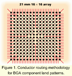
 前面的例子是针对使用标准多层板的周围引脚包装的。当把裸芯片上的绑接座移动到阵列模式的位置而设计再分配层时这些规则发生戏剧性的变化。另外,从阵列元件的内焊盘出来的出口线的布线密度,可能不提供传统的
1, 2, 3 或 4 导线的布线机会(图一)。高密度内连接(HDI, high-density interconnect)技术在改变配线要求能力上扮演戏剧性的角色。 前面的例子是针对使用标准多层板的周围引脚包装的。当把裸芯片上的绑接座移动到阵列模式的位置而设计再分配层时这些规则发生戏剧性的变化。另外,从阵列元件的内焊盘出来的出口线的布线密度,可能不提供传统的
1, 2, 3 或 4 导线的布线机会(图一)。高密度内连接(HDI, high-density interconnect)技术在改变配线要求能力上扮演戏剧性的角色。
定义标准化的要求
J-STD-012 和 -013 都不是传统的标准。每一个都促成什么标准需要开发来让下部结构(infractructure)去遵守的讨论。在早期,只有那些具有良好技术资源的公司才能供应得起对未证实的技术的投资。另外,行业内也都在实行外部采办,所以选错伙伴可能会损失惨重。
每一个 J 标准都定义一个发展计划。需要用于实施的标准被确认,并选择了范围和用途。对每个方案指定一个唯一编号,而不确定什么标准开发组织将担任领导角色。其结论可成为
J, IPC, EIA(Electronic Industries Alliance) 或 JEDEC(Joint Electronic
Device Engineering Council) 的标准。
| Table
3, J-STD-012 Projects - Work in Progress |
| Project
Number |
Assigned
Number |
Description
of Activity |
Status |
| P101 |
J-STD-026 |
Semiconductor
design standard for flip chip application |
Released |
| P102 |
J-STD-027 |
Mechnical
outline standard for flip chip or chip scale configurations |
Working
draft 95% |
| P103 |
J-STD-028 |
Performance
standard for flip chip/chip scale bumps |
Released |
| P104 |
J-STD-029 |
Test
methods for chip scale and BGA products and assembly |
Working
draft 95% |
| P105 |
|
Flip
chip/chip scale carrier trays(JEDEC) |
JC
11.5 |
| P106 |
|
Bare
dice as flip chip or chip scale configuration management
standard(JEDEC) |
JC
11.4 |
| P107 |
IPC-2225 |
Design
standard for single and multiple chip package printed
boards |
Released |
| P108 |
IPC-6015 |
Performace
requirements for single and multiple chip package printed
board structures |
Released |
| P109 |
IPC- |
Qualification
and performance standard for flip chip inorganic mounting
structures |
Not
started HM-840? |
| P110 |
IPC-TM-650 |
Test
methods for qualification and evaluation of flip chip
mounting structures |
Defined
in HDI docs |
| P111 |
IPC-7076
IPC-7078
|
Requirements
for chip scale/chip size component package mounting
Requirements
for flip chip component package mounting(DCA)
|
Working
draft First proposal |
| P112 |
IPC- |
Standard
for flip chip/chip scale assembly performance requirements |
Not
started |
| P113 |
Add
to J-STD-029 |
Test
methods for qualification and evaluation of flip chip/chip
scale assemblies |
Working
draft 80% |
| P114 |
IPC- |
Standard
for flip chip/chip scale assembly rework and repair |
Not
started |
| P115 |
IPC- |
Flip
chip/chip scale assembly reliability standard |
Not
started |
| P116 |
J-STD-030 |
Qualification
and performance of flip chip underfill materials |
Proposal |
| P117 |
|
Qualification
and performance of flip chip passivation materials |
Not
started |
| P118 |
|
Qualification
and performance of flip chip encapsulation materials |
Not
started |
| P119 |
|
Qualification
and performance for adhesives used in flip chip assembly
|
Not
started |
| P120 |
J-STD-004 |
Qualification
and performance of flux used in flip chip assembly(also
IEC 61190-1-1) |
Revision
working |
|
表三显示了 J-STD-012(IEC PAS 62084) 所确认的20个方案的状态。表四显示了 J-STD-013(IEC
PAS 62085)所确认的11个方案的状态。每个由SMC所协调的J标准都已由国际电子技术委员会(International
Electrotechnical Commission)作为一个公共可利用规范(PAS, publicly availabe
specification)出版。PAS规则允许标准开发者许可原版文件的国际再版,因此其它国家的专业人员可得到同样的信息。
| Table
3, J-STD-013 Projects - Work in Progress |
| Project
Number |
Assigned
Number |
Description
of Activity |
Status |
| P201 |
J-STD-031 |
Design
standard for BGA applications |
Working
draft 10% |
| P202 |
J-STD-032 |
Performance
standard for BGA bumps and columns |
Working
draft 95% |
| P207 |
IPC-2226 |
Design
tandard for HDI PCBs |
Working
draft 40% |
| P208 |
IPC-6016 |
Qualification
and performance specifiction for HDI layers or boards |
Interim
final |
| P209 |
|
Qualification
and performance specifiction for BGA inorganic mounting
structures |
Not
started |
| P210 |
IPC-TM-650 |
Test
methods for qualification and evaluation of BGA mounting
structures |
Difined
in HDI docs |
| P211 |
IPC-7075 |
Requirements
for high-pin-count area-array component mounting
|
First
proposal |
| P212 |
IPC-7095 |
Design
and assembly process implementation for BGAs |
Released |
| P213 |
Add
to J-STD-029 |
Test
methods for qualification and evaluation of BGA assemblies |
Working
draft 80% |
| P214 |
IPC-7711 |
Standard
for BGA assembly rework and repair techniques |
Published |
| P216 |
J-STD-004
|
Qualification
and performance of flux used in BGA chip assembly
(also IEC 61190-1-1)
|
Updating
required |
|
最好的还有待出台
 一组专业献身的个人刚完成
IPC-7095, Design and Assembly Process Implementation for BGAs《BGA的设计与制造工艺实施标准》。在Ray
Prasad 的领导下,来自 Celestica, Intel, Merix, Amkor, RadiSys, Tektronix,
Micron 和 Glenbrook Technology 的专家开发了一个文件,确认所以实施BGA技术的要求。 一组专业献身的个人刚完成
IPC-7095, Design and Assembly Process Implementation for BGAs《BGA的设计与制造工艺实施标准》。在Ray
Prasad 的领导下,来自 Celestica, Intel, Merix, Amkor, RadiSys, Tektronix,
Micron 和 Glenbrook Technology 的专家开发了一个文件,确认所以实施BGA技术的要求。
IPC-7095描述了实施BGA和密间距BGA(FBGA)技术的设计与装配的挑战。也叙述了BGA和FBGA对现有技术和元件类型的影响。这个文件的重点在临界检查、修复和与BGA有联系的可靠性问题。
 IPC-7095
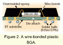
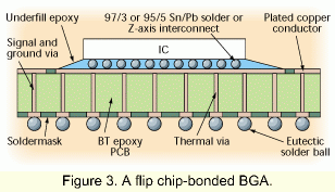
的目标使用者是经理、设计与工艺工程师和从事电子装配、检查与修理过程的操作员和技术员。目的是为那些使用BGA或正考虑实施的人提供有用的和实际的信息。该文件提供了有关裸芯片怎样附着到板层的见解。图二和三显示了在BGA制造中使用的配线绑接(wiring-bonded)和倒装芯片的构造。 IPC-7095
的目标使用者是经理、设计与工艺工程师和从事电子装配、检查与修理过程的操作员和技术员。目的是为那些使用BGA或正考虑实施的人提供有用的和实际的信息。该文件提供了有关裸芯片怎样附着到板层的见解。图二和三显示了在BGA制造中使用的配线绑接(wiring-bonded)和倒装芯片的构造。
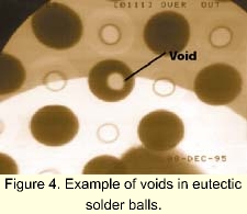
 除了各种产品描述之外,IPC-7095
也提供了对BGA附着中空洞的信息与讨论。图四显示一个X光用来测定BGA球界面中的空洞的存在和尺寸。 除了各种产品描述之外,IPC-7095
也提供了对BGA附着中空洞的信息与讨论。图四显示一个X光用来测定BGA球界面中的空洞的存在和尺寸。
更多的有关IPC7095的信息,请联系IPC的顾客服务部,电话:(847) 790-5362。行业应该感谢那些个人的辛勤工作和贡献,他们的名字列在每个标准的致谢页内。
DIETER BERGMAN, is director of technology transfer for
the IPC -- Association Connecting Electronics Industries, 2215
Sanders Road, Northbrook, IL 60062; (847) 509-9700; Fax: (847)
509-9798.
(A 11/11/2000)
|

